
In this article, we will configure the GRE (Generic Routing Encapsulation) tunnel between two Cisco Routers. GRE is developed by Cisco System. In order to configure the GRE tunnel, you must need connectivity between two remote routers through static Public IP address. So, let’s configure the GRE Tunnel. GRE usages IP protocol number 47. By default, GRE does not perform any kind of encryption. Although, you can configure the GRE Tunnel over the IPSec VPN for securing the GRE tunnel. GRE is initially defined in rfc1701.
Scenario for GRE (Generic Routing Encapsulation) Tunnel
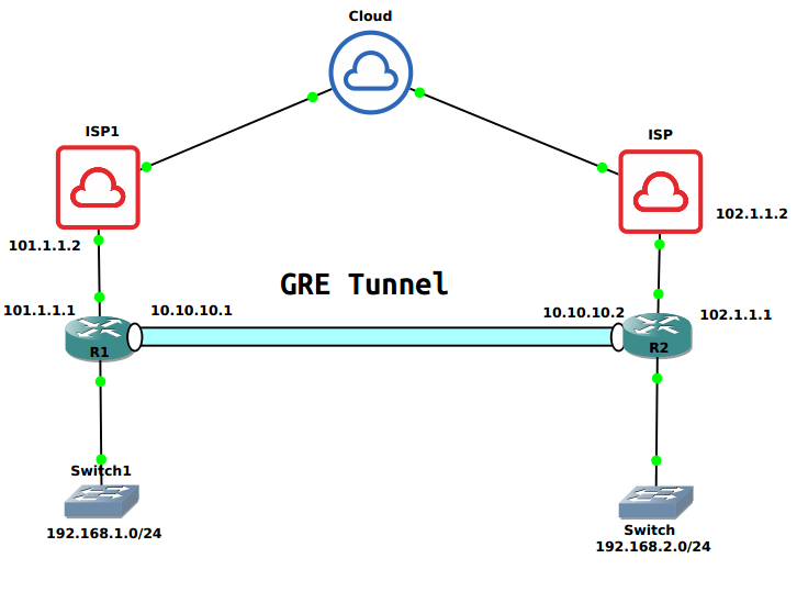
I have two different routers in two different locations. Router R1 has Public IP 101.1.1.1 and Router R2 has Public IP 102.1.1.1. R1 and R2 can communicate using their Public IP addresses. Both routers R1 and R2, have their LAN Network subnet 192.168.1.0/24 and 192.168.2.0/24 respectively. We will use another subnet 10.10.10.0/30 which is used for GRE tunnel interfaces.
So, configuring the GRE tunnel by checking the connectivity between routers. Just open the console of nay router and ping another end router.
[terminal]R1#ping 102.1.1.2
Type escape sequence to abort.
Sending 5, 100-byte ICMP Echos to 102.1.1.2, timeout is 2 seconds:
!!!!!
Success rate is 100 percent (5/5), round-trip min/avg/max = 8/11/16 ms
R1#[/terminal]
How to configure GRE Tunnel on Cisco Routers
Configuring the Router Interfaces
First of all, we need to configure the Network Interfaces on both of the Routers. So let’s configure the Network Interfaces on Router R1. Go to the global configuration mode and enter the following commands:
[terminal]interface FastEthernet0/0
ip address 192.168.1.1 255.255.255.0
no shutdown[/terminal]
[terminal]interface FastEthernet1/0
ip address 101.1.1.1 255.255.255.252
no shutdown[/terminal]
Now, let’s configure the Router Interfaces of Router R2.
[terminal]interface FastEthernet0/0
ip address 192.168.2.1 255.255.255.0
no shutdown[/terminal]
[terminal]interface FastEthernet1/0
ip address 102.1.1.1 255.255.255.252
no shutdown[/terminal]
Configuring the GRE Tunnel
Now, we will configure the GRE tunnel interface. It is always recommended to provide a different subnet for both the peer ends. In this example, I’m taking 10.10.10.0/30 network. On router R1, I configured tunnel interface 100 and IP address 10.10.10.1/30. Along with the IP address, you also need to configure local and remote public IP addresses as well. So, open the router’s global configuration mode and run the following commands in global configuration mode.
You can choose tunnel interface between 0-2147483647 depends on your router capacity.
Configuring GRE Tunnel Interface on Router R1:
[terminal]interface Tunnel100
ip address 10.10.10.1 255.255.255.252
tunnel source 101.1.1.1
tunnel destination 102.1.1.1[/terminal]
Configuring GRE Tunnel Interface on Router R2:
[terminal]interface Tunnel100
ip address 10.10.10.2 255.255.255.252
tunnel source 102.1.1.1
tunnel destination 101.1.1.1[/terminal]
Create Static routes for GRE Destination Network
Now, we need to configure a static route for the Peer LAN subnet. We need to define the tunnel interface as an exit interface for the destination network. Just, go to router global configuration mode and run the following command. The first route is the default route pointing to the ISP and another one is the route for the GRE Peer end LAN subnet.
You can also configure Dynamic Routing Protocols between GRE Peers.
Routes on Router R1:
[terminal]ip route 0.0.0.0 0.0.0.0 101.1.1.2
ip route 192.168.2.0 255.255.255.0 Tunnel100[/terminal]
Routes on Router R2:
[terminal]ip route 0.0.0.0 0.0.0.0 102.1.1.2
ip route 192.168.1.0 255.255.255.0 Tunnel100[/terminal]
Verification of Configuration done on both Peers
Now, we have finished the configuration between both the GRE Neighbors. Now, we will initiate a ping for the Router R1 and verify our configuration. Access the CLI of any of the router and initiate a ping to the GRE LAN Subnet.
[terminal]R1#ping 192.168.2.1 source 192.168.1.1[/terminal]
If your configuration is perfect, you will receive the ping response messages.
[terminal]R1#ping 192.168.2.1 source 192.168.1.1
Type escape sequence to abort.
Sending 5, 100-byte ICMP Echos to 192.168.2.1, timeout is 2 seconds:
Packet sent with a source address of 192.168.1.1
!!!!!
Success rate is 100 percent (5/5), round-trip min/avg/max = 4/25/32 ms
R1#[/terminal]
Related Articles
- IPv4: Internet Protocol Version 4 (Explained with Header)
- How to configure GRE Tunnel Between Palo Alto and Cisco Router
References
Summary
In this article, we configured the GRE tunnel on Cisco Routers. GRE tunnel is a kind of VPN which can provide the connectivity between two remote locations. By default, GRE does not perform any kind of encryption. However, it can also be configured over IPSec VPN to perform encryption. In order to configure the GRE tunnel, two remote locations must be reachable through a static Public IP.
Did you enjoyed this article? If you are facing any issue during GRE Tunnel configuration, please leave a comment in comment box!
Nice blog. I understood the concept very well. This blog is very informative. And it’s very interesting topic.